


Home » Technical-Screw Jack Operation Manual
Technical-Screw Jack Operation Manual
Caution: Read this manual before installation or operation of JACTON screw jacks. Failure to understand this manual, installation or operation screw jack properly could result in damage to the jack and or serious personal injury.
1. Do not exceed the jack ratings including design load capacity, travel length, and input speed. Install, align and shield all moving parts properly. Proper machinery installation practices should be followed. Safety codes for mechanical power transmissions apparatus are to be followed. Check for and adhere to all applicable safety codes. Bolts should be sized to fit the jack mounting holes, at least grade 5 and tightened to the appropriate torque. Mounting bases should be flat and sufficiently strong to support the load. Properly lubricate and maintain the JACTON product. Use the jack only for the intended application. Failure to install, use, or maintain JACTON products could result in product failure and personal injury.
2. This operation manual is applicable to all jacks models. Note: Information represents typical configuration and may difference slightly from the actual jack being installed or repaired. The maintenance instruction provides recommendations of safe and efficient approach to installation or service repair problems.
When an operating situation occurs, refer to the troubleshooting guide to isolate cause. When applicable, guides are listed by symptom followed with suggestions of probable causes.
3. Once the source of the problem is identified, consult JACTON engineers for disassembly and re-assembly procedures guides for recommended repair procedures.
General Instruction and Specifications
Your screw jack was manufactured to high quality standards and is designed to provide many hours of service. But certain safety measures and procedures must be followed in handling, installing and servicing the jack to insure long trouble free service.
1. Any obvious or suspected damage to jack during transport from the factory must be immediately reported to JACTON company and the carrier.
2. Upon delivery all of the jack should be inventoried to determine if shortages exist. All shortages must be immediately reported to JACTON company and the carrier.
3. The installation jack supplied by JACTON company does not include the services of a field engineer.
4. The warranty applies only if the jack is operated within the rated capacity and conditions for which the jack was specifically designed. The application design engineer must prevent any destructive conditions for the jacks. Conditions that may be considered destructive are: excessive input speeds, extreme shock loading, mechanical or thermal overloading, exceeding recommended duty cycles, and side loading of the load screw.
5. Installation, maintenance and safety instructions must be given to personnel directly responsible for the installation, maintenance and operation of the jack.
6. In the event that a malfunction of the jack occurs within the warranty period JACTON company must be informed immediately and the jack must be immediately removed from service.
Caution: screw jack is normally self-locking feature. Vibration could cause the screw jack to self lower or creep. In the absence of internal or external stops the load screw can be moved out of the jack base. Your jack base is not equipped with internal stop nuts unless special requirements in your order. Jacks are not meant for personnel support. All applications designed for personnel support must be approved by JACTON company engineers.
The worm gear driven screw jack incorporates incorporates a heat treatment standard No.45 steel worm which drives a high tensile bronze worm gear, accurately machined to the high standards of JACTON Company for maximum load carrying capacity and uniformity of motion transmission. All shafts of jt-series screw jacks are mounted on heavy duty tapered roller bearings, and all shafts of jtw-series screw jacks and jtc series screw jacks are mounted on thrust bearings to increase operating efficiency of the drive mechanism. Heavy duty tapered roller bearings of jt-series screw jacks, and thrust bearings of jtw-series screw jacks and jtc series screw jacks are provided to support the rated thrust load of each screw jack. Housings are made of ductile iron are designed to handle the rated thrust load and torque loads of each screw jack size.
A protective tube is furnished which is threaded into the jack in order to keep the load screw threads dust-proof and lubricated. The load screw is made of high quality standard No.45 steel that is ground to size and precision rolled to form the threads. They are well proportioned to handle the maximum lifting force of the jack. Stainless steel or special customized load screws can be provided at an additional cost. The threads of the load screw should be well lubricated and kept free of grit and dirt. Bellow boots can be provided as an accessory to protect the exposed portion of the load screw. In the event of over travel the boots may be crushed. Standard jacks may be operated at a wide range of input speeds. All jacks are recommended based on customer supplied duty cycle requirements.
Installation Instructions
1. Be certain that the rating of the jack exceeds the maximum load that may be imposed upon it.
2. Check that rated input speeds of the jack will not be exceeded. Verify in the jack catalog technical datas pages.
3. The foundation for the jack must be rigid enough to maintain correct alignment with connected machinery and have ample strength to carry the maximum load.
4. The foundation should have a flat mounting surface to uniformly support the jack. The opening for the load screw cover (or load screw) that passes through jack base must be as small as possible to provide jack support over the largest possible area.
5. Check that the method of stopping the screw rotation so translation will occur is sufficiently strong.
6. It is extremely important that the jack be installed so that the load screw is exactly plumb and that all connecting shafts is aligned with the worm shaft.
7. After precise alignment, each member must be securely bolted and if possible, doweled in place. Doweling will assure exact repositioning if ever removed. It is essential that a jack.
8. After the jacks, bevel gearboxes, connecting shafts and couplings are installed and aligned, there should be no signs of binding or misalignment.
9. Connecting shafts and couplings are the responsibility of the customerS and are not provided by JACTON, unless specifical requirements in your order.
10. Cautions must be taken when operating your jack at either extreme of travel. If possible, hard external stops should be provided.
11. If operating at the upper limits of the jack rating, don't stop the downward travel of the jack by running the load screw attachments or the load against the housing without checking with JACTON, as serious damage to the internal mechanism may result.
12. The customer is responsible for providing mechanical stops and limit switches for control of the prime travel length. None are included unless specifical requirements in your order.
Very Important: take up evenly on mounting bolts to avoid damaging the housing.
Cautions:
1. If limit switches are furnished by JACTON, they are JACTON set only for controlling two positions such as full extend or full retract.
2. The foundation of the jack is critical to insure alignment. Mount the jack and check that the axis of the load screw is parallel to the movement of the load and centered with respect to the load. Shim under the base to achieve this if needed. Both eccentric loading and/or side loading will cause premature wear and possible bending and failure of the jack. Once the alignment is correct hand tighten the mounting bolts.
3. Next align the input shafts with the worm shaft of the jack. This alignment can be just as critical to proper operation. Test the alignment by rotating the shafts by hand, and fully extend the load screws. If the hand operation turns freely and the other components of the system are in alignment, tighten the mounting fasteners and attach the load to the jack. Start-up should be and break-in periods of several minutes with careful observation are required. Any vibrations, binding or excessive amperage draw of motors is reason to shut down and repeat the entire alignment procedure.
4. Finally the load screw should be re-greased when using, and the jack housing be checked that it is full of grease.
Trouble Shooting
Your jacks will perform satisfactorily if the suggestions described in the booklet are carefully followed. It is estimated the approximately 98 percent of screw jack failures can be attributed to improper lubrication, misapplication, and misalignment.
Housing Failure
Inspection Point: 1. Jack Overload; 2. Improper Support; 3. High Shock; 4. Uneven Bolting Torque.
Solutions: 1. Reduce load or replace with unit of sufficient capacity; 2. Jack should be supported over entire base area, not just at bolt hole locations; 3. Select larger Unit; 4. Take up evenly on mounting bolts.
Worm Shaft Failure
Inspection Point: 1. Type of Coupling; 2. Coupling Alignment; 3. Excessive Overhung Load; 4. Jack Overload; 5. Shock Loading; 6. "Ganging" Jacks.
Solutions: 1. Rigid Couplings can cause shaft Failure. Replace with coupling which will provide adequate flexibility and lateral float; 2. Re-align as required; 3. Check Jack for allowable loads; 4. Reduce load or replace with unit of sufficient capacity; 5. Install coupling capable of absorbing shock and if necessary replace with jack of sufficient capacity. Shock loads can significantly increase apparent dead weight; 6. If several jacks are in-line, the worm shaft of the first jack will be subjected to the combined torque of all the jacks. If this torque exceeded 300% of the rated input torque you must replace with a larger jack.
Bearing Failure
Inspection Point: 1. Jack Overload; 2. Coupling Alignment; 3. Excessive Overhung Load; 4. Coupling Lateral Alignment; 5. Bearing Adjustment; 6. Bearing Lubrication; 7. Shock Loading.
Solutions: 1. Reduce load or replace with unit of sufficient capacity; 2. Re-align as required; 3. Check Jack for allowable loads; 4. Adjust spacing between connecting shafts to relieve end pressure; 5. Bearings must be preloaded; 6. Proper levels and grade must be maintained at all times; 7. Install coupling capable of absorbing shock and if necessary replace with jack of sufficient capacity. Shock loads can significantly increase apparent dead weight.
Worm Gear Failure
Inspection Point: 1. Jack Overload; 2. Load Screw Alignment; 3. Lubrication; 4. Duty Cycle Limit Exceeded; 5. Side load.
Solutions: 1. Reduce load or replace with unit of sufficient capacity; 2. Lifting Screws must be perfectly plumb; 3. Proper levels and grade must be maintained at all times; 4. Reduce the number of cycles per hour or reduce the load. Contact factory for the maximim allowable cycles per hour; 5. Eliminate side load.
Lubricant
1. The lubricant should not be corrosive to gears, ball or roller bearings and must be neutral in reaction. The lubricant must not contain any contamination that may be detrimental to operation of the jack. The lubricant must have resistance to oxidation and must be non-channeling. Operating temperatures must be considered when selecting a lubricant for a jack. We recommended the following extreme pressure synthetic grease or their equivalents. For applications outside these limits contact the JACTON engineers.
2. The jack working temperature -20 deg. C to +80 deg. C, synthetic grease extreme pressure No.2 grease, super high or low temperature, need special grease, please contact JACTON engineers.
3. JACTON jacks are shipped with grease. Lubricant inspection is recommended at regular intervals. Intervals are determined by the duty cycles of the jacks but should be performed a minimum of once every two months.
4. Each jack is furnished with a grease fitting. The jack should be filled with grease until lubricant begins to seep from the load screw opening. For jacks with bellow boots, remove the bellow boots at the jack before you check for proper grease levels. Severe operating conditions may require more frequent lubrication.
5. Load screws must be checked regularly to insure that they are adequately lubricated. This is especially critical for the rotating screw design units where no lubrication is deposited because the load screw does not translate through the housing into the protective tube.
Disassembly Of Travelling Nut Rotating Screw Design
1. Remove the boot clamps and collapse boots, if the jack is equipped with boots. Remove the traveling nut from the screw.
2. Loosen the set screws in the housing cover and remove the housing cover by rotating counter-clockwise (CCW.)
3. The screw assembly can now be removed from the jack sleeve. The screw assembly consists of the lifting screw, the upper thrust bearing / tapered roller bearing (jtw series jack and jtc series jack with thrust bearing, jt series jacks with tapered roller bearing), the key and the wormgear. The upper thrust bearing / tapered roller bearing can be removed from the assembly. The wormgear can be pressed off the screw for replacement if necessary. Note: On inverted rotating screw jacks models, it may be necessary to remove the screw first.
4. Remove screws from the bearing cover. Remove the bearing covers and seals carefully to avoid damaging seals. Make sure keys have been removed first.
5. Carefully remove the shims from the jack sleeve or bearing cover. Note: there will not necessarily be an equal quantity of shims per side. Keep track of the number and order of shims on each side of the jack.
6. Remove the worm bearings. The cup may be press-fit and require the use of a dead-blow, plastic or other non-marring mallet to remove the worm.
Disassembly Of Translating Screw Design
1. Remove the boot clamps and collapse the boot if equipped. On upright and inverted models, loosen the set screws and remove the housing cover by rotating CCW.
2. Remove the protection tube and check to see if the lifting screw has travel stops. This may require the use of a pipe wrench or strap wrench. If the jack has travel stops on the screw, these will need to be removed before the lifting screw is removed from the jack. If the jack does not have stops, the lifting screw can be removed by simply unthreading it from the wormgear.
3. Remove the thrust bearing / tapered roller bearing (jtw series jack and jtc series jack with thrust bearing, jt series jacks with tapered roller bearing) and the wormgear from the sleeve. The bearing cones may be pressed onto the wormgear.
4. Keyed jacks have a keyway cut the length of the lifting screw. The steel housing cover has a key, which travels in the keyway and prevents rotation of the lifting screw. It is very important to prevent any side load on a keyed jack, as the key can cut into the lifting screw, and severely affect the life of the jack.
5. Remove screws, from the bearing covers. Remove the bearing covers and seals carefully to avoid damaging seals. Make sure keys have been removed first.
6. Carefully remove the shims from the jack sleeve or bearing cover. Note: there will not necessarily be an equal quantity of shims per side. Keep track of the number and order of shims on each side of the jack.
7. Remove the worm shaft bearings. The cups may be press-fit and require the use of a dead-blow, plastic or other non-marring mallet to remove the worm.
Assembly Inspection
Caution: Never perform any work on the jack or associated transmission equipment until the prime travel length cannot be remotely or automatically started. Make sure the load is properly supported before the Jack, brake, or other holding devices are removed. Be sure the area around the Jack is relatively clean to prevent the parts from becoming contaminated, and the machined parts are stored on wooden blocks to prevent damage to the machined surfaces.
1. If possible remove the jack from the structure and inspect the jack on a work bench. If not use cribbing to support the load.
2. Clean the jack of grease, dirt, and foreign material
3. Visually inspect the jack for damage such as cracked, broken or chipped parts, and married surfaces.
4. Using a soft cloth or tape to protect the input shaft, with a pair of pliers or by hand, attempt to turn the input shaft. If it won't turn without extreme effort, total disassembly will be required. Consulting JACTON engineers for the disassembly procedure.
5. Measure the rotary backlash: Rig a positive stop and extend the load screw against the stop. Mark the position of the input shaft. Reverse the rotation of the input shaft until you feel the beginning of the load screw movement. Again mark the position of the input shaft. Measure the angle of this rotation. If the measurement exceeds the 60 degrees then the worm shaft and the worm gear must be replaced.
6. Measure the axial backlash: Extend the load screw against the positive stop. Mark and remove the positive stop. Protect the load screw with a soft cloth or tape, clamp a handle to the load screw and pull the load screw in the direction of the removed stop. Measure the movement to determine the axial movement. If the movement is greater then the allowable limits, the worm gear and the load screw should be replaced.
Assembly
1. Insure that all bearings are packed with grease. Coat seals with light oil and put masking tape on keyways and other sharp surfaces to avoid seal damage.
2. Assembly of jack is reverse of the disassembly procedure. Make sure all bearings and seals seat properly. The bearing cover screws and housing cover should only be hand tightened, initially. Some jacks may require the wormgear and thrust bearing / tapered roller bearing (jtw series jack and jtc series jack with thrust bearing, jt series jacks with tapered roller bearing) be installed first, as they will not pass the worm, if already installed.
3. Tighten bearing cover bolts. Check the input shaft for excessive axial or lateral movement. If the input shaft feels loose remove shims, if it feels tight, add shims. Give the input shaft a solid blow on each end (in axial direction) with a soft mallet and recheck the feel. If it feels OK, continue to next step, otherwise continue adjusting the shims. This is a trial and error operation. The correct set-up has a solid feel without play (axial or lateral) and the input shaft rotates with an even, smooth but snug feel.
4. When jack is re-assembled, the thrust bearing / tapered roller bearing (jtw series jack and jtc series jack with thrust bearing, jt series jacks with tapered roller bearing) pre-load needs to be set. Check by rotating the input shaft, while tightening the housing cover. Continue to check the rotation of the input shaft as housing cover is tightened. Use a dead-blow hammer on top of housing cover to help it seat. Tighten housing cover until it will not tighten further by hand.
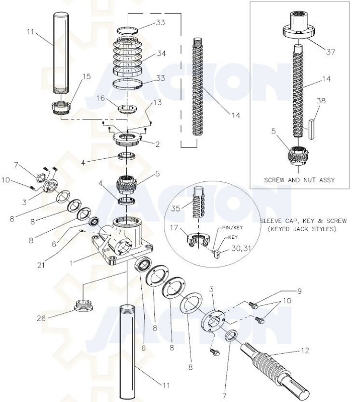
| 1 | housing | 2 | housing cover | 3 | bearing cover |
| 4 | thrust bearing / tapered roller bearing | 5 | worm gear | 6 | worm shaft bearing |
| 7 | worm shaft seal | 8 | shims | 9 | bearing cap lockwasher |
| 10 | bearing cap screw | 11 | protective tube | 12 | worm shaft |
| 13 | set screw for housing cover | 14 | lifting screw | 15 | protective tube adapter (inverted only) |
| 16 | seal | 17 | keyed housing cover | 26 | bushing (inverted only) |
| 30 | key - keyed jacks | 31 | key screw - keyed jacks | 33 | bellows boot clamp |
| 34 | bellows boot | 35 | keyed screw | 37 | traveling nut |
| 38 | key - rotating jacks |
Product List
Manual Electric Screw Jack
Worm Screw Jack
- JTC Cubic Screw Jack
- JTM Worm Screw Jack
- JSS Stainless Steel Jack
- JT Acme Screw Jack
- JTW Machine Screw Jack
- Through Holes Screw Jack
- Custom Made Screw Jack
Ball Screw Jack
Bevel Gear Jack
Miter Gearbox
- JT Classic Miter Gearbox
-
- Order Code for Classic Miter Gearbox
- Classic Miter Gearbox description
- JT15 Miter Gearbox
- JT19 Miter Gearbox
- JT25 Miter Gearbox
- JT32 Miter Gearbox
- JT40 Miter Gearbox
- JT45 Miter Gearbox
- JT50 Miter Gearbox
- JT60 Miter Gearbox
- JT72 Miter Gearbox
- JT85 Miter Gearbox
- Flange Input Solid Output Shaft Gearbox
- JTP Cubic Miter Gearbox
-
- Order Code for Cubic Miter Gearbox
- Cubic Miter Gearbox description
- JTP65 Small Miter Gearbox
- JTP90 Miter Gearbox
- JTP110 Miter Gearbox
- JTP140 Miter Gearbox
- JTP170 Miter Gearbox
- JTP210 Miter Gearbox
- JTP240 Miter Gearbox
- JTP280 Miter Gearbox
- Solid Input and Output Shafts Gearbox
- Solid Input and Hollow Output Gearbox
- Flange Input and Solid Output Gearbox
- Flange Input and Hollow Output Gearbox
- JTA Alu. Miter Gearbox
Lift System and Accessories
- Screw Jack System
- Lift System Accessories
-
- Flexible Jaw Coupling
- Overload Safety Couplings
- Aluminum Couplings
- Telescopic Universal Joint
- Rigid Shaft Couplings
- Universal Joint
- Cast Iron Hand Wheel
- Connecting Shafts
- Aluminum Handwheel
- YVF2 Series Variable Speed AC Motor
- Brake motors
- Three Phase Electric Motor
- Screw Jack Motor Flange
- Single Phase Induction Motors
- K Helical Bevel Geared Motor
- R Helical Geared Motor
- Worm Gear Reducer
- 12V 24V DC Geared Motor
- Proximity Switches
- Limit Switches
- Pillow Blocks
- Pillow Block Flange Bearing
- Digital Position Indicator
- Flange Blocks
- Ball Joint Rod End Bearing
- Bellows Boot
- Helical Gear Motor
- 12V 24V DC Motor
- Linear Bushings and Shafts
- Trunnion Adapters
- Servomotor
- Rotary Encoder
- Low Backlash Planetary Gearheads
- Stepper Motor
- 24V Planetary Gear Reducer
- Planetary Speed Reducer
- Frequency Inverter
- Hydraulic Cylinder Rod End Bearing
- Lift System Applications
Linear Actuators
- LAP Electric Linear Actuator
-
- 100KG Parallel Electromechanical Linear Actuators
- 250KG Parallel Electro Mechanical Linear Actuators
- 500KG Parallel Mount Rod Style Linear Actuators
- 630KG Parallel Mount Electric Cylinder Linear Actuators
- 1000KG Parallel Mount Industrial Linear Actuators Acme Screw
- 1600KG Parallel Electro-mechanical Actuators Heavy Duty
- 2500KG Parallel Mount Electric Cylinders Actuator
- 4000KG Heavy Duty Electric Linear Actuators Parallel Mount
- 6300KG Parallel Motor Drive Electric Actuator Linear Actuator
- 8000KG Parallel Electric Motor-Drive Linear Actuator
- 10000KG Parallel Mount Motorized Electric Linear Actuator
- 15000KG Parallel Industrial Motor Linear Actuator
- 20000KG Parallel Indistrial Motor Drive Linear Actuator
- 25000KG Parallel Electric Motor Linear Electric Actuator
- LA Electric Linear Actuators
-
- 10KG In-line Mini Electric Linear Actuators with Brake Motor
- 25KG In-line Electric Linear Actuator Push Rod
- 63KG In-line 700mm Stroke Electric Motor Linear Actuator
- 90KG In-line High Speed Motor Drive Electric Linear Actuator
- 100KG In-line Fast Speed Electric Linear Motor Linear Actuator
- 300KG Inline Industrial Electromechanical Linear Actuator
- 500KG In-Line Electric Linear Actuator
- 700KG Inline Heavy Electro Mechanical Actuators
- 1000KG In-line Heavy Duty AC Volt Industrial Linear Actuators
- JTE Classic Electric Cylinder
- Mechanical Linear Actuators
- JCA Cubic Electric Cylinder
Application


Jacton Industry Co.,Ltd.
 Contact: Warren Lee
 Skype: jactonjack
 T: 86-769-81585810
 F: 86-769-81585852
 E: sales@jactonindustry.com
 W: www.screw-jack.com


Contact: Warren LeeSkype: jactonjackT: 86-769-81585810 F: 86-769-81585852 E: sales@jactonindustry.com W: www.screw-jack.com
VAT No. 9144190007026567X3, Copyright ©2013 www.screw-jack.com Jacton Industry Co.,Ltd. All Rights Reserved Site Map
Building 2, No. 1, DongCheng Road, Chang An, Dongguan, Guangdong, China. Phone: 86-769-81585810 | Fax: 86-769-81585852
China Screw Jack,Ball Screw Jack,Machine Screw Jack,Worm Gear Screw Jack,Bevel Gear Screw Jack,Miter Gearbox,Screw Jack Lift System Manufacturer
China Screw Jack,Ball Screw Jack,Machine Screw Jack,Worm Gear Screw Jack,Bevel Gear Screw Jack,Miter Gearbox,Screw Jack Lift System Manufacturer