


Home» Spiral Bevel Gearboxes sets the standard for 1:1 and 2:1 spiral bevel gear drives. » Product Detail
Products
 |
THE NAME:
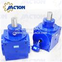
1 to 1.5 speed increaser gearbox
Model: 1 to 1.5 speed increaser gearbox
Place of Origin: Made In China
Brand Name: JACTON
Download: 


Description:
Pictures
Features
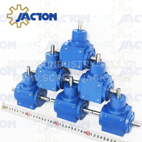
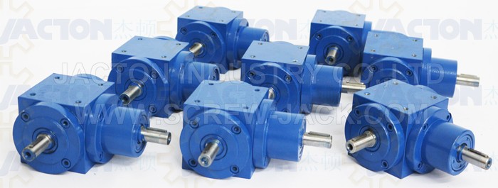
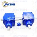
1. JTP series cubic gearbox has 8 models, they are JTP65, JTP90, JTP110, JTP140, JTP170, JTP210, JTP240, JTP280.
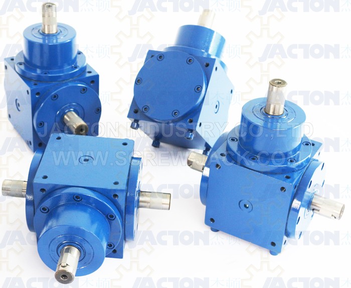
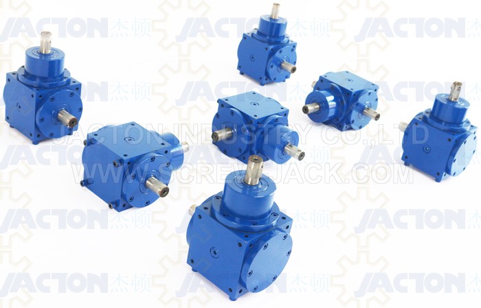
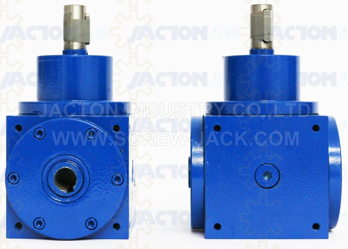
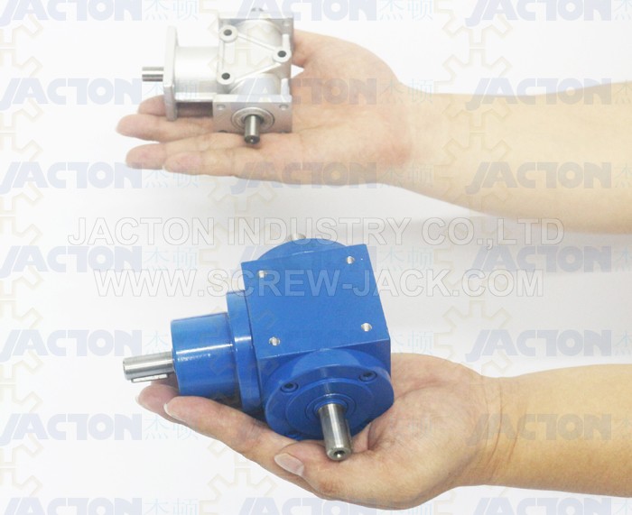
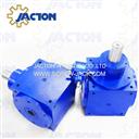
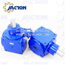
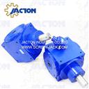
2. Ultra compact cubic bevel gearbox design, all-round machined symmetrical housing, and all-round tapped holes for universal mounting, 6 possible universal mounting positions, can be easily mounted in any direction.
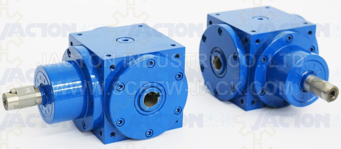
3. Configuration available solid input and output shaft, solidinput shaft with output hollow shaft, input IEC flange with output solid shaft, input IEC flange with output hollow shaft.
4. With various types are standardized, all gear ratios of 1:1, 1.5:1, 2:1, 3:1, 4:1 and 5:1 are actual ones. Average efficiency is 98%.
5. 2 way, 2 way reverse, 3 way, 3 way reverse, 4 way and 4 way reverse configurations.
6. Allowable torque 40Nm to 1199Nm, power 6kw-156kw, input speed 0-1500rpm.
7. Low backlash, quiet low noise, low running temperature, lubricants prior to shipment, factory tested prior to shipment.
8. Mainly applicate in screw jack lift system, printing press, plastic extruder, sewage auger, bonding equipment, metering auger, sewage agitator, newspaper conveyor, bottling equipment, material handling, web finishing, paper conveying, conveyor, cardboard box equipment, packaging, vertical pump drive, sand spreader, residential mower, snow blower, mining equipment, crane, agricultural, grain wagon, harvester, forage harvester, manure spreader, fertilizer spreader and sewage conveyor etc.
Structures and Materials
Structures: cubic gearbox or housing, spiral bevel gears, input shafts, output shafts, bearings, sealings, shafts covers etc.
Spiral Bevel Gears
1. High purity rugged alloy steel 20CrMnTiH material
2. Carburizing process, case hardened and lapped in pairs for intersecting shafts
3. Low noise with grinded spiral teeth, high torque with milled teeth, high rigidity and wear risistance
Input Shaft and Output Shaft
1. Hardened and tempered alloy steel 40Cr material, hanging heavy load capacity With key and keyway
2. Customized stainless steel, chromium coated or other corrosion resistance painting.
3. Customized spline shaft,shaft without key and keyway
Cubic Gearbox or Housing
1. High rigidity cast iron
2. Customized stainless steel, galvanic coating or other corrosion resistance painting
Bearing
1. Heavy duty tapered roller bearing
2. Customized reinforced bearings for higher radial and axial load
Oil Seal
1. Double lip oil seal
2. Prevent gear oil leak and dustproof
Models and Specifications
Example Selection Guide
JTP90 – 1:1 – C – B3
1 2 3 4
1. Model
Model: JTP65, JTP90, JTP110, JTP140, JTP170, JTP210, JTP240, JTP280
2. Gear Ratio
1:1, 1.5:1, 2:1, 3:1, 4:1, 5:1
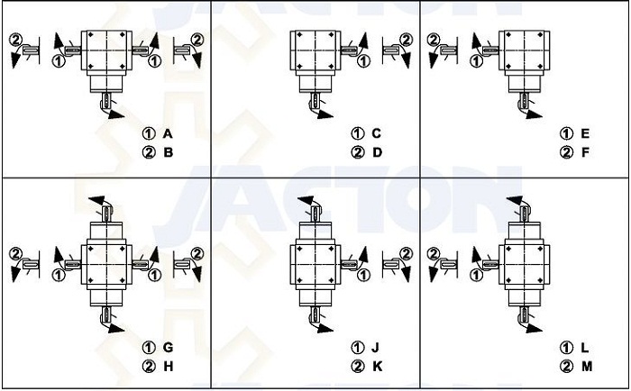
3. Shaft Arrangements And Direction Of Shaft Rotating
Drive shafts can be rotated in both forward and reverse directions. CW=Clockwise, CCW=Counterclockwise.
* A: 3 way, input shaft CW, output shaft CW.
* B: 3 way reverse, input shaft CW, output shaft CCW.
* C: 2 way, input shaft CW, right side output shaft CW.
* D: 2 way reverse, input shaft CW, right side output shaft CCW.
* E: 2 way, input shaft CW, left side output shaft CW.
* F: 2 way reverse, input shaft CW, left side output shaft CCW.
* G: 4 way, input shaft CW, inline input shaft CCW, output shaft CW.
* H: 4 way reverse, input shaft CW, inline input shaft CCW, output shaft CCW.
* J: 3 way, input shaft CW, inline input shaft CCW, right side output shaft CW.
* K: 3 way reverse, input shaft CW, inline input shaft CCW, right side output shaft CCW.
* L: 3 way, input shaft CW, inline input shaft CCW, left side output shaft CW.
* M: 3 way reverse, input shaft CW, inline input shaft CCW, left side output shaft CCW
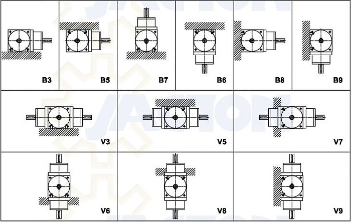
4. Mounting Position
* Horizontal mount codes: B3, B7, V3, V6
* Over hung mount codes: B5, B6, V5, V8
* Wall mount codes: B8, B9, V7, V9
Features
1. JTP series cubic gearbox has 8 models, they are JTP65, JTP90, JTP110, JTP140, JTP170, JTP210, JTP240, JTP280.
2. Ultra compact cubic bevel gearbox design, all-round machined symmetrical housing, and all-round tapped holes for universal mounting, 6 possible universal mounting positions, can be easily mounted in any direction.
3. Configuration available solid input and output shaft, solidinput shaft with output hollow shaft, input IEC flange with output solid shaft, input IEC flange with output hollow shaft.
4. With various types are standardized, all gear ratios of 1:1, 1.5:1, 2:1, 3:1, 4:1 and 5:1 are actual ones. Average efficiency is 98%.
5. 2 way, 2 way reverse, 3 way, 3 way reverse, 4 way and 4 way reverse configurations.
6. Allowable torque 40Nm to 1199Nm, power 6kw-156kw, input speed 0-1500rpm.
7. Low backlash, quiet low noise, low running temperature, lubricants prior to shipment, factory tested prior to shipment.
8. Mainly applicate in screw jack lift system, printing press, plastic extruder, sewage auger, bonding equipment, metering auger, sewage agitator, newspaper conveyor, bottling equipment, material handling, web finishing, paper conveying, conveyor, cardboard box equipment, packaging, vertical pump drive, sand spreader, residential mower, snow blower, mining equipment, crane, agricultural, grain wagon, harvester, forage harvester, manure spreader, fertilizer spreader and sewage conveyor etc.
Structures and Materials
Structures: cubic gearbox or housing, spiral bevel gears, input shafts, output shafts, bearings, sealings, shafts covers etc.
Spiral Bevel Gears
1. High purity rugged alloy steel 20CrMnTiH material
2. Carburizing process, case hardened and lapped in pairs for intersecting shafts
3. Low noise with grinded spiral teeth, high torque with milled teeth, high rigidity and wear risistance
Input Shaft and Output Shaft
1. Hardened and tempered alloy steel 40Cr material, hanging heavy load capacity With key and keyway
2. Customized stainless steel, chromium coated or other corrosion resistance painting.
3. Customized spline shaft,shaft without key and keyway
Cubic Gearbox or Housing
1. High rigidity cast iron
2. Customized stainless steel, galvanic coating or other corrosion resistance painting
Bearing
1. Heavy duty tapered roller bearing
2. Customized reinforced bearings for higher radial and axial load
Oil Seal
1. Double lip oil seal
2. Prevent gear oil leak and dustproof
Models and Specifications
| JTP65 Mini Miter Gearbox 1. gear ratio 1:1 2. cubic,6 mount positions 3. solid input,output shaft 4. 2 way,3 way,4 way shafts 5. input power max. 1.8Kw 6. drive torque max. 13.5Nm | JTP90 Miter Gearbox 1. gear ratios 1:1 to 5:1 2. cubic,6 mount positions 3. solid shaft,hollow shaft 4. 2 way,3 way,4 way shafts 5. input power max. 6Kw 6. drive torque max. 43.3Nm | JTP110 Miter Gearbox 1. gear ratios 1:1 to 5:1 2. cubic,6 mount positions 3. solid shaft,hollow shaft 4. 2 way,3 way,4 way shafts 5. input power max. 11Kw 6. drive torque max. 78.3Nm |
| JTP140 Miter Gearbox 1. gear ratios 1:1 to 5:1 2. cubic,6 mount positions 3. solid shaft,hollow shaft 4. 2 way,3 way,4 way shafts 5. input power max. 23.9Kw 6. drive torque max. 170Nm | JTP170 Miter Gearbox 1. gear ratios 1:1 to 5:1 2. cubic,6 mount positions 3. solid shaft,hollow shaft 4. 2 way,3 way,4 way shafts 5. input power max. 39.2Kw 6. drive torque max. 290Nm | JTP210 Miter Gearbox 1. gear ratios 1:1 to 5:1 2. cubic,6 mount positions 3. solid shaft,hollow shaft 4. 2 way,3 way,4 way shafts 5. input power max. 67.5Kw 6. drive torque max. 520Nm |
| JTP240 Miter Gearbox 1. gear ratios 1:1 to 5:1 2. cubic,6 mount positions 3. solid shaft,hollow shaft 4. 2 way,3 way,4 way shafts 5. input power max. 90.5Kw 6. drive torque max. 694Nm | JTP280 Miter Gearbox 1. gear ratios 1:1 to 5:1 2. cubic,6 mount positions 3. solid shaft,hollow shaft 4. 2 way,3 way,4 way shafts 5. input power max. 156Kw 6. drive torque max. 1199Nm |
Example Selection Guide
JTP90 – 1:1 – C – B3
1 2 3 4
1. Model
Model: JTP65, JTP90, JTP110, JTP140, JTP170, JTP210, JTP240, JTP280
2. Gear Ratio
1:1, 1.5:1, 2:1, 3:1, 4:1, 5:1
3. Shaft Arrangements And Direction Of Shaft Rotating
Drive shafts can be rotated in both forward and reverse directions. CW=Clockwise, CCW=Counterclockwise.
* A: 3 way, input shaft CW, output shaft CW.
* B: 3 way reverse, input shaft CW, output shaft CCW.
* C: 2 way, input shaft CW, right side output shaft CW.
* D: 2 way reverse, input shaft CW, right side output shaft CCW.
* E: 2 way, input shaft CW, left side output shaft CW.
* F: 2 way reverse, input shaft CW, left side output shaft CCW.
* G: 4 way, input shaft CW, inline input shaft CCW, output shaft CW.
* H: 4 way reverse, input shaft CW, inline input shaft CCW, output shaft CCW.
* J: 3 way, input shaft CW, inline input shaft CCW, right side output shaft CW.
* K: 3 way reverse, input shaft CW, inline input shaft CCW, right side output shaft CCW.
* L: 3 way, input shaft CW, inline input shaft CCW, left side output shaft CW.
* M: 3 way reverse, input shaft CW, inline input shaft CCW, left side output shaft CCW
4. Mounting Position
* Horizontal mount codes: B3, B7, V3, V6
* Over hung mount codes: B5, B6, V5, V8
* Wall mount codes: B8, B9, V7, V9
Previous Product:1.5 to 1 gear reduction ratio bevel gearbox
Next Product:1 1.5 speed increasing bevel gear box

Product List
Manual Electric Screw Jack
Worm Screw Jack
- JTC Cubic Screw Jack
- JTM Worm Screw Jack
- JSS Stainless Steel Jack
- JT Acme Screw Jack
- JTW Machine Screw Jack
- Through Holes Screw Jack
- Custom Made Screw Jack
Ball Screw Jack
Bevel Gear Jack
Miter Gearbox
- JT Classic Miter Gearbox
-
- Order Code for Classic Miter Gearbox
- Classic Miter Gearbox description
- JT15 Miter Gearbox
- JT19 Miter Gearbox
- JT25 Miter Gearbox
- JT32 Miter Gearbox
- JT40 Miter Gearbox
- JT45 Miter Gearbox
- JT50 Miter Gearbox
- JT60 Miter Gearbox
- JT72 Miter Gearbox
- JT85 Miter Gearbox
- Flange Input Solid Output Shaft Gearbox
- JTP Cubic Miter Gearbox
-
- Order Code for Cubic Miter Gearbox
- Cubic Miter Gearbox description
- JTP65 Small Miter Gearbox
- JTP90 Miter Gearbox
- JTP110 Miter Gearbox
- JTP140 Miter Gearbox
- JTP170 Miter Gearbox
- JTP210 Miter Gearbox
- JTP240 Miter Gearbox
- JTP280 Miter Gearbox
- Solid Input and Output Shafts Gearbox
- Solid Input and Hollow Output Gearbox
- Flange Input and Solid Output Gearbox
- Flange Input and Hollow Output Gearbox
- JTA Alu. Miter Gearbox
Lift System and Accessories
- Screw Jack System
- Lift System Accessories
-
- Flexible Jaw Coupling
- Overload Safety Couplings
- Aluminum Couplings
- Telescopic Universal Joint
- Rigid Shaft Couplings
- Universal Joint
- Cast Iron Hand Wheel
- Connecting Shafts
- Aluminum Handwheel
- YVF2 Series Variable Speed AC Motor
- Brake motors
- Three Phase Electric Motor
- Screw Jack Motor Flange
- Single Phase Induction Motors
- K Helical Bevel Geared Motor
- R Helical Geared Motor
- Worm Gear Reducer
- 12V 24V DC Geared Motor
- Proximity Switches
- Limit Switches
- Pillow Blocks
- Pillow Block Flange Bearing
- Digital Position Indicator
- Flange Blocks
- Ball Joint Rod End Bearing
- Bellows Boot
- Helical Gear Motor
- 12V 24V DC Motor
- Linear Bushings and Shafts
- Trunnion Adapters
- Servomotor
- Rotary Encoder
- Low Backlash Planetary Gearheads
- Stepper Motor
- 24V Planetary Gear Reducer
- Planetary Speed Reducer
- Frequency Inverter
- Hydraulic Cylinder Rod End Bearing
- Lift System Applications
Linear Actuators
- LAP Electric Linear Actuator
-
- 100KG Parallel Electromechanical Linear Actuators
- 250KG Parallel Electro Mechanical Linear Actuators
- 500KG Parallel Mount Rod Style Linear Actuators
- 630KG Parallel Mount Electric Cylinder Linear Actuators
- 1000KG Parallel Mount Industrial Linear Actuators Acme Screw
- 1600KG Parallel Electro-mechanical Actuators Heavy Duty
- 2500KG Parallel Mount Electric Cylinders Actuator
- 4000KG Heavy Duty Electric Linear Actuators Parallel Mount
- 6300KG Parallel Motor Drive Electric Actuator Linear Actuator
- 8000KG Parallel Electric Motor-Drive Linear Actuator
- 10000KG Parallel Mount Motorized Electric Linear Actuator
- 15000KG Parallel Industrial Motor Linear Actuator
- 20000KG Parallel Indistrial Motor Drive Linear Actuator
- 25000KG Parallel Electric Motor Linear Electric Actuator
- LA Electric Linear Actuators
-
- 10KG In-line Mini Electric Linear Actuators with Brake Motor
- 25KG In-line Electric Linear Actuator Push Rod
- 63KG In-line 700mm Stroke Electric Motor Linear Actuator
- 90KG In-line High Speed Motor Drive Electric Linear Actuator
- 100KG In-line Fast Speed Electric Linear Motor Linear Actuator
- 300KG Inline Industrial Electromechanical Linear Actuator
- 500KG In-Line Electric Linear Actuator
- 700KG Inline Heavy Electro Mechanical Actuators
- 1000KG In-line Heavy Duty AC Volt Industrial Linear Actuators
- JTE Classic Electric Cylinder
- Mechanical Linear Actuators
- JCA Cubic Electric Cylinder
Application


Jacton Industry Co.,Ltd.
 Contact: Warren Lee
 Skype: jactonjack
 T: 86-769-81585810
 F: 86-769-81585852
 E: sales@jactonindustry.com
 W: www.screw-jack.com


Contact: Warren LeeSkype: jactonjackT: 86-769-81585810 F: 86-769-81585852 E: sales@jactonindustry.com W: www.screw-jack.com
VAT No. 9144190007026567X3, Copyright ©2013 www.screw-jack.com Jacton Industry Co.,Ltd. All Rights Reserved Site Map
Building 2, No. 1, DongCheng Road, Chang An, Dongguan, Guangdong, China. Phone: 86-769-81585810 | Fax: 86-769-81585852
China Screw Jack,Ball Screw Jack,Machine Screw Jack,Worm Gear Screw Jack,Bevel Gear Screw Jack,Miter Gearbox,Screw Jack Lift System Manufacturer
China Screw Jack,Ball Screw Jack,Machine Screw Jack,Worm Gear Screw Jack,Bevel Gear Screw Jack,Miter Gearbox,Screw Jack Lift System Manufacturer